Laser Tag
Introduction
A laser tag system based on an AVR microcontroller - specifically, the AVR Atmel ATmega328p. For prototyping I’m using an Arduino Uno board, but I plan to make a custom circuit board with the microcontroller placed directly on it. The software is written in C and does not use the Arduino/Wiring library - it uses AVR libc directly. This means the code has direct control over the timers, interrupts and other features of the microcontroller, which allows many improvements over existing AVR-based systems I have seen (e.g. the code is capable of simultaneous infrared reception and transmission).
Technical details
Infrared communication
The infrared signals are encoded on top of a 38 kHz carrier wave. A packet starts with a 1200 microsecond burst and is then followed by 16 more bursts, each representing a single bit. A burst of 800 microseconds indicates a binary 1, a burst of 400 microseconds indicates a binary 0. There is a 400 microsecond gap between these bursts. The most significant bit is sent first and the least significant bit is sent last.
This is similar to the underlying protocol used by other hobby Laser Tag systems, however, not quite compatible (due to the fixed 16 bit length and slightly different timings to account for the properties of the detector). The protocol that is eventually used on top of this will probably vary significantly from that of other systems - interoperability is not a concern of this project.
A Vishay TSAL6100 infrared LED is actually used for transmission. A timer on the AVR chip is used to generate the 38 kHz carrier, and the software turns the carrier on and off at the appropriate times to generate the bursts. Vishay TSOP4838 sensors are used for reception. These demodulate the signal such that their output is low when the carrier is on, and high when the carrier is off. An interrupt is fired on a rising and falling edge, and some simple timing and decoding code allows the packet to be read.
LCD screen
The LCD screen uses a Hitachi HD44780-compatible controller connected to a 74HC595 shift register to conserve pins on the AVR chip. The code can only write commands/data to the controller because of this, but all of the required functionality can be implemented without read support.
Speaker
The speaker is connected to a pin, which in turn is connected to a timer. The timer is configured to produce a square wave at varying frequencies, so a variety of flat tones can be generated, but no complex waveforms.
LEDs
The LEDs are connected to a 74HC595 shift register, just like the LCD screen. There are two LEDs for each team (red, green, blue, yellow) giving eight in total. The code implements an alternate flashing effect for the team colour. In the future, for complex game modes, a particular colour could signal someone as having captured the flag, for example.
Connected directly to the AVR chip there is also a muzzle flash LED with a small viewing angle and high intensity.
Radio communication
In order for live scoring/hit feedback, complex game modes, etc., radio communications between the guns and a central server computer will be used. I’m currently looking at using HopeRF RFM12B chips for this.
Photos
|
This photo shows the original version of the infrared circuit using a 555 timer to generate the 38 kHz carrier, which was made before I was aware that an internal timer on the AVR chip could accomplish this. |
|
This is the newer version of the infrared circuit that uses an internal timer so it is a lot simpler. The current through the infrared LED is limited to 50mA by the resistor network, at the time I did not have the correct value resistor for this, and in the future a transistor will be added so higher currents can be used (the LED is capable of up to 200 mA). |
|
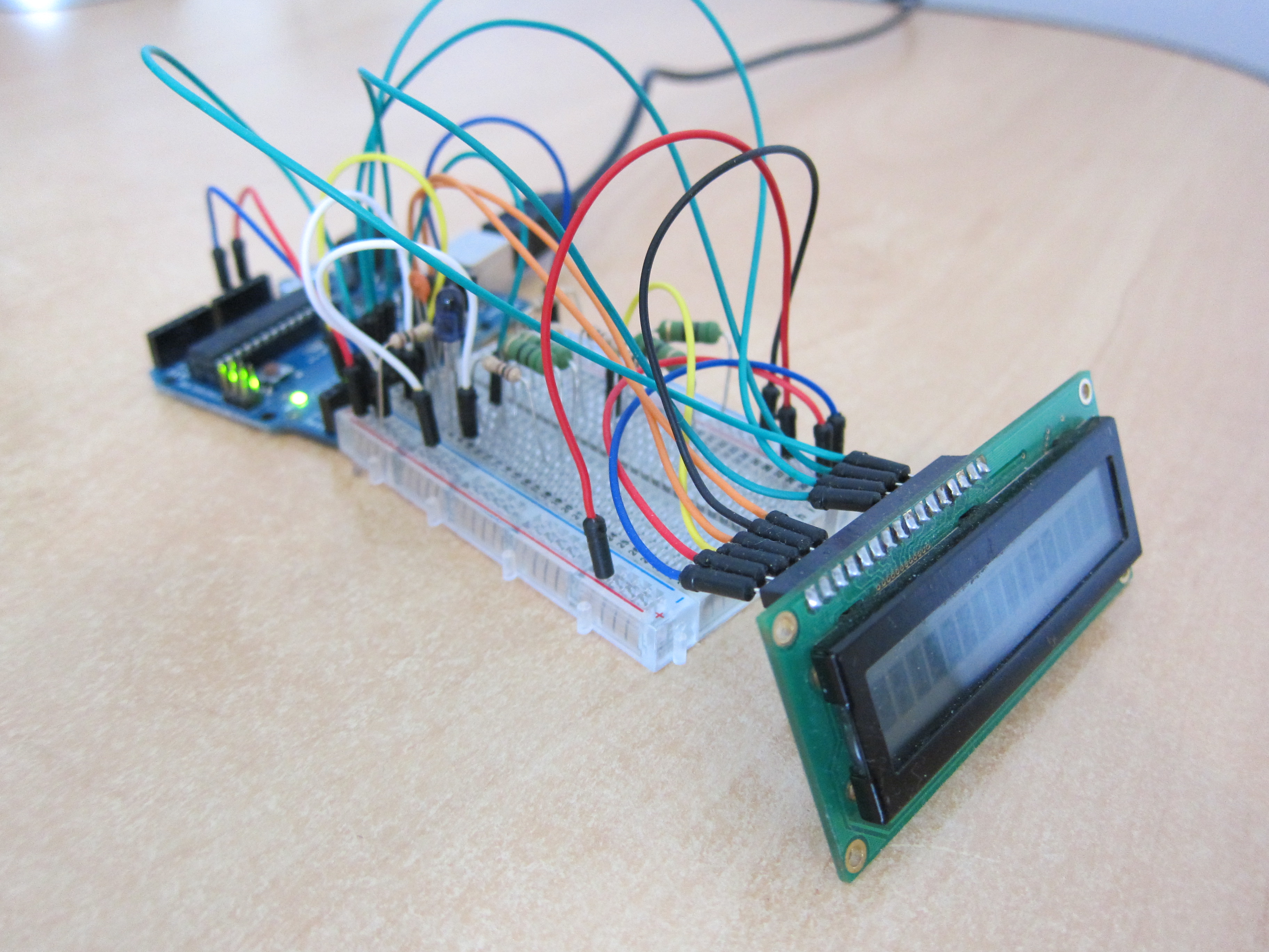
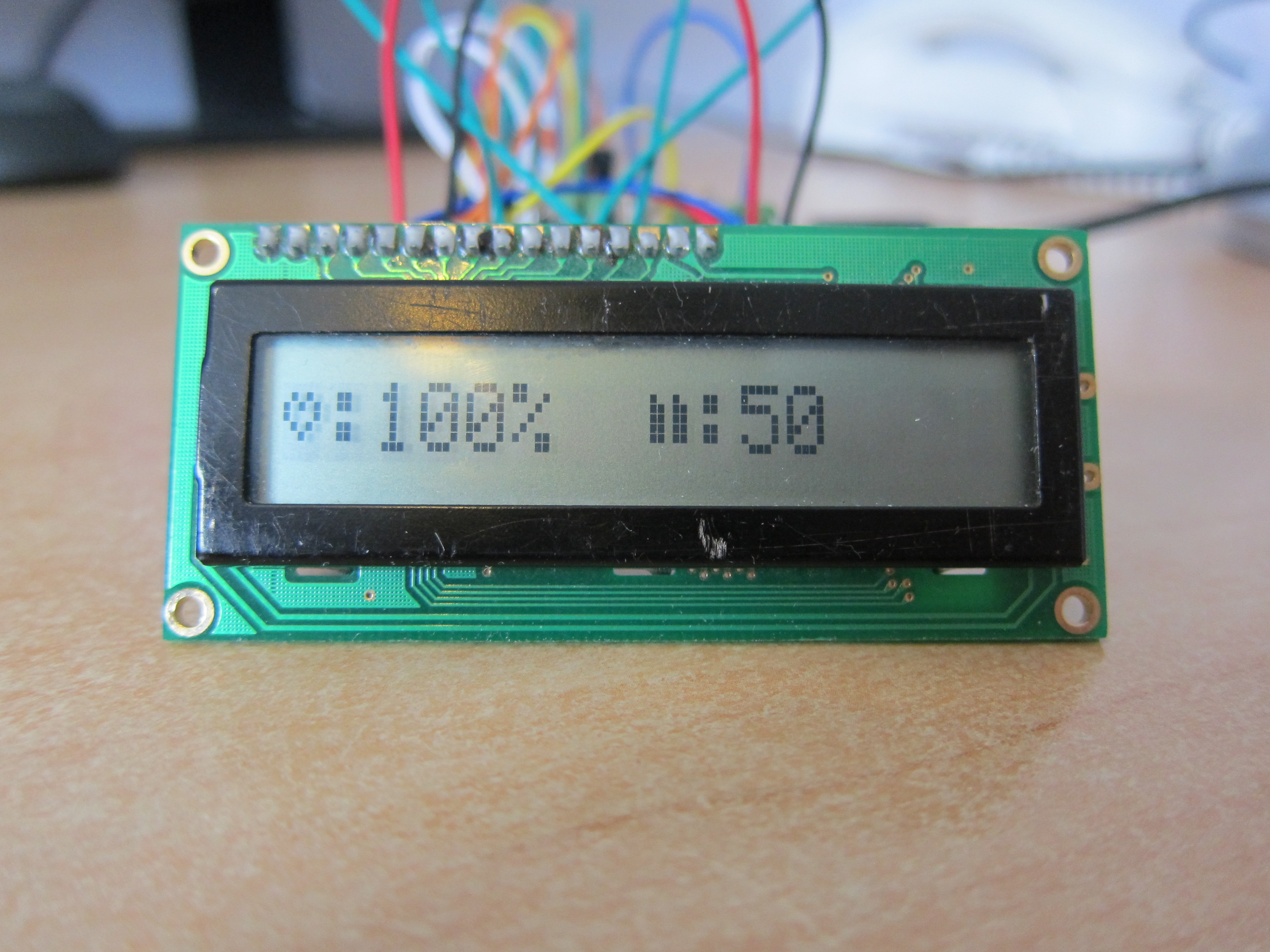
This shows an LCD display using a HD44780-compatible controller, interfacing with the AVR chip in 4-bit mode. |
|
This shows a health display on the left side and ammo display on the right side. The icons are implemented as custom characters in the controller's character generation RAM. |
|
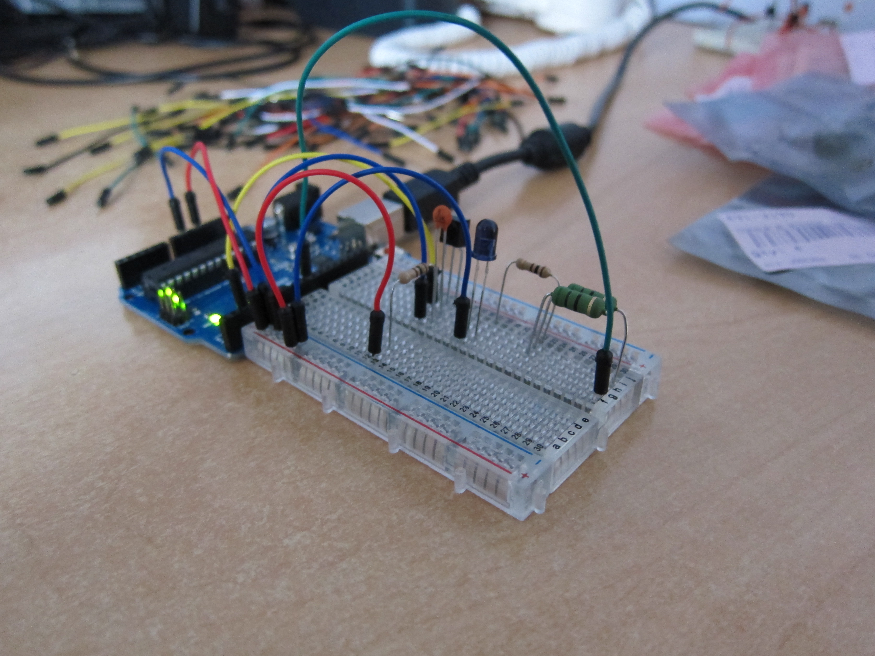
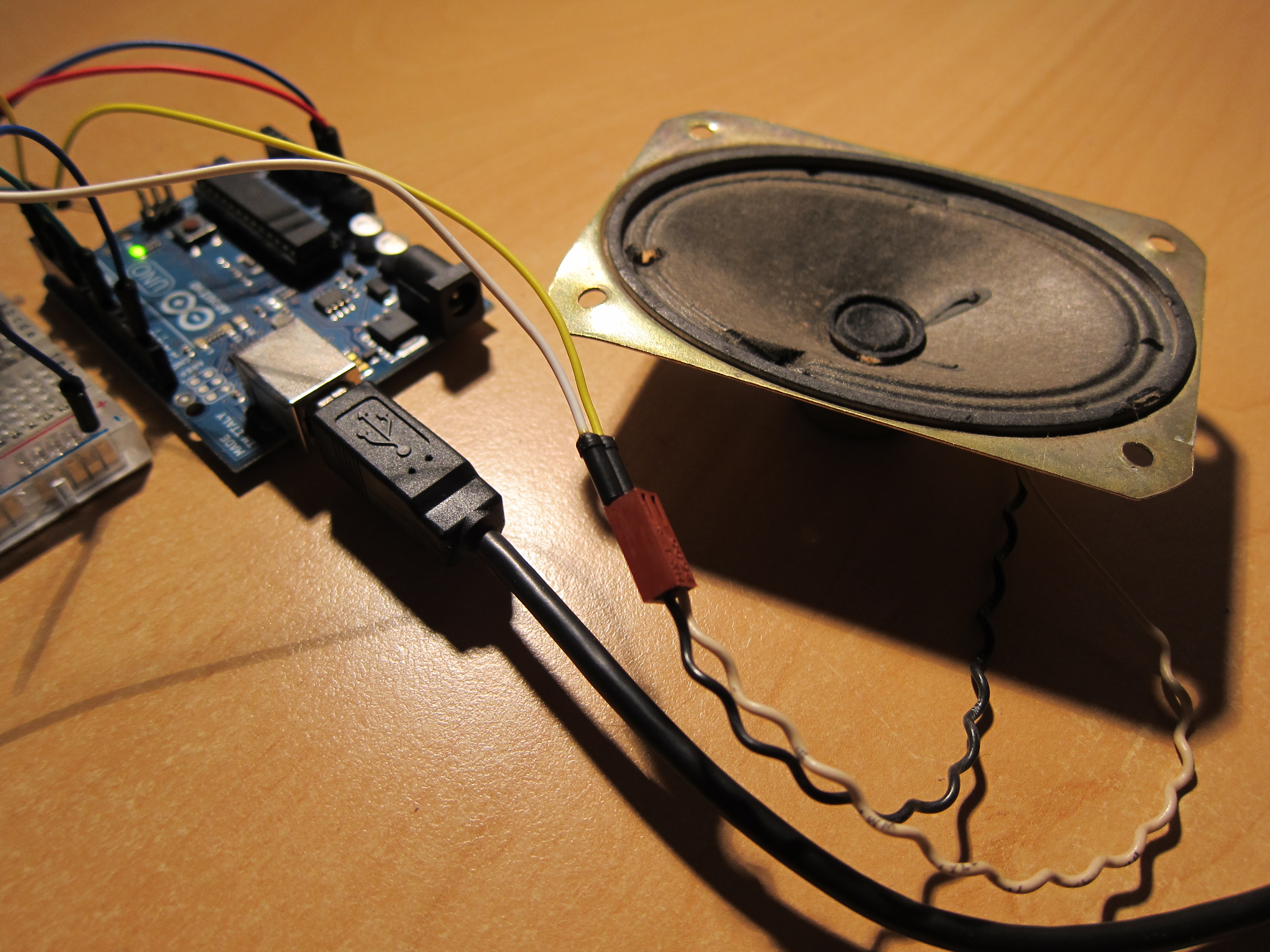
This shows a speaker being used to generate tones of various frequencies using one of the AVR timers. |
|
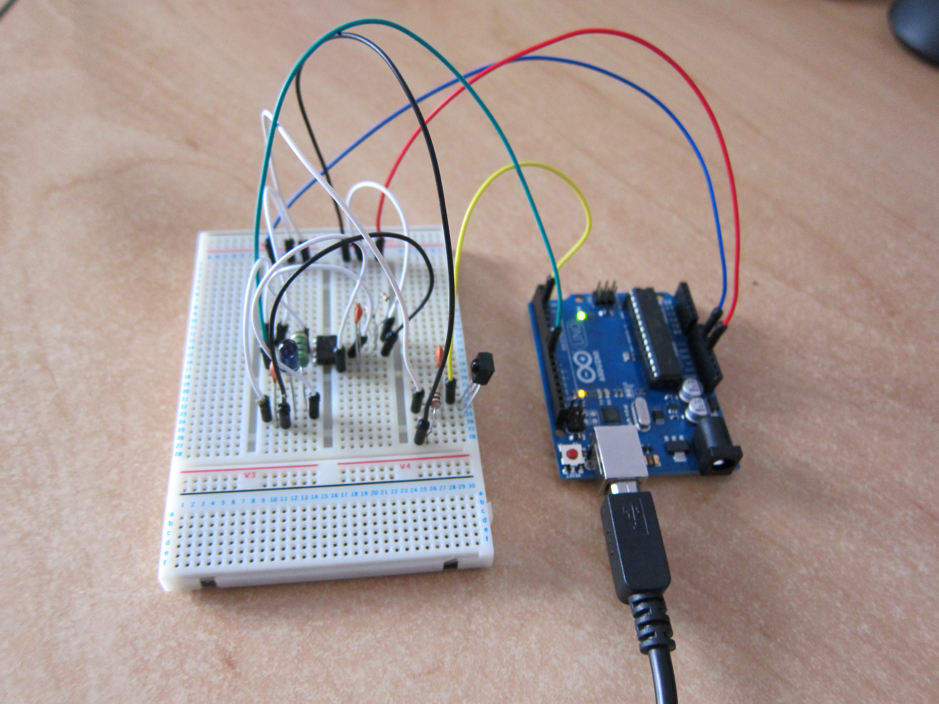
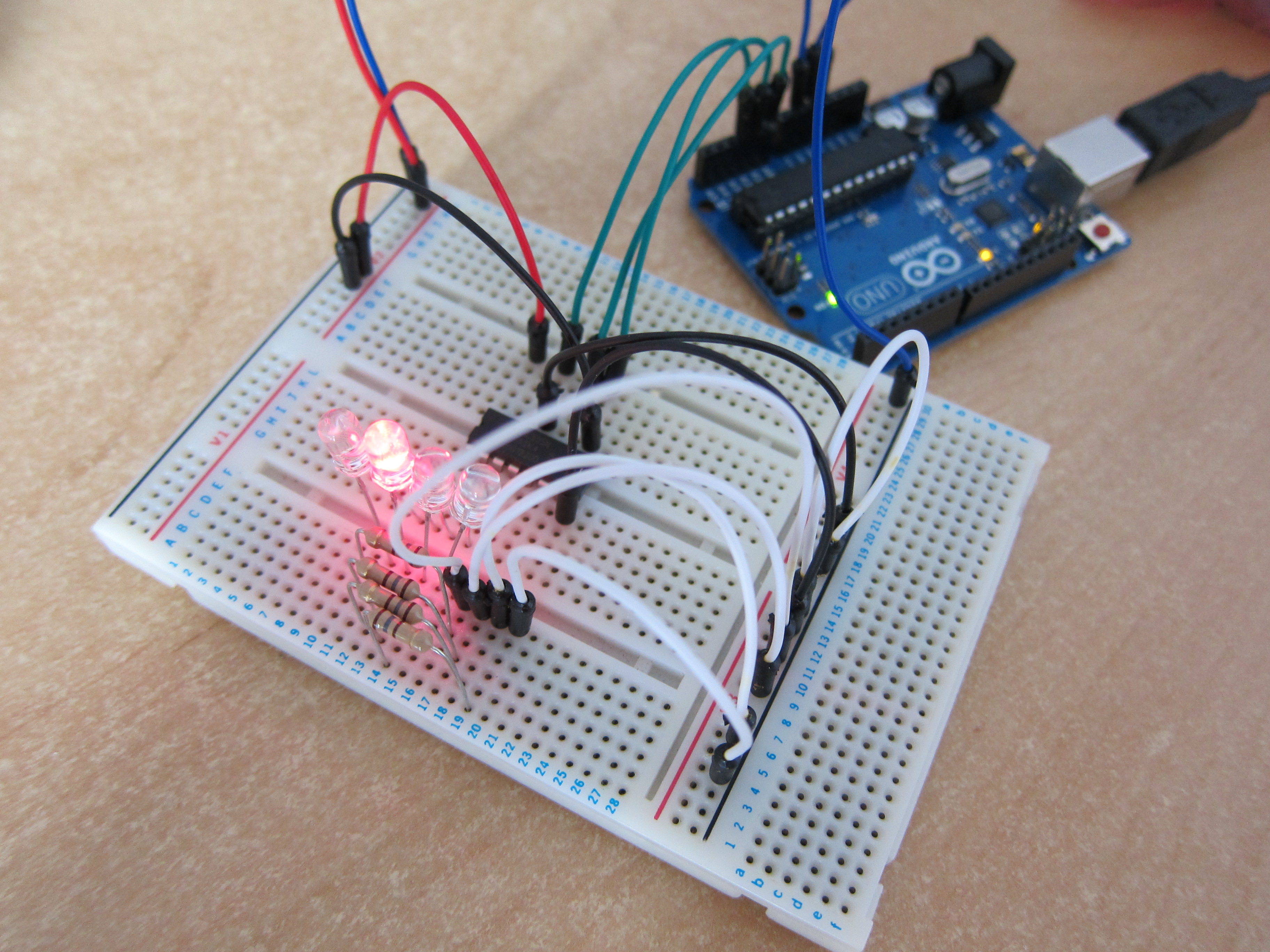
This is a picture of a temporary circuit used to test the shift register code. The AVR chip does not quite have enough pins for the whole planned circuit, so shift registers will be used for things like status LEDs to free up pins for other purposes. |

|
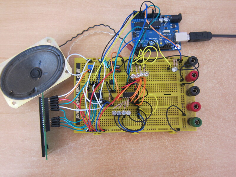
This is a near-complete prototype of the circuit (it lacks the RFM12B radio chip as that uses 2mm pitch instead of 2.54mm, so I can't easily breadboard it, and also lacks the buttons, as I almost ran out of wires.) It features the infrared circuitry (including MOSFET), LCD screen, speaker, team indicator LEDs and muzzle flash LED. |
Source code
The work-in-progress code is available on GitHub.